Cautions in Using The Switch
General
- The appearance and specifications of the product may be modified to improve its performance without prior notice.
- This catalog shows only outline specifications. When using the product, please obtain formal specifications.
- Regardless of the applications of these products being introduced in this catalog, when using them for equipments and devices requiring a high degree of safety, respective manufacturers shall preserve the safety of the planned equipments and devices by providing necessary protective and redundancy circuits and reconfirm if safety is being duly preserved.
- Products being introduced in this catalog have been designed and manufactured for the applications to ordinary electronic equipments and devices such as AV equipments, electric home appliances, office machines and communication equipments. Consequently, when using these products for the applications requiring a high degree of safety and reliability such as medical equipments, aviation and aircraft equipments, space equipments and burglar alarm equipments, the manufacturers shall thoroughly study the proprieties of these products for the planned applications.
- Although we are exerting our best efforts to maintain the quality of these switches, we cannot guarantee that they will never cause short- circuit and open circuitry. Therefore, when designing an equipment or device of which priority is the safety, you shall carefully study the influences to the whole equipment of a single function failure of a switch in advance to make out a fail-safe design providing necessary protective circuits.
- The general-use switches cannot be washed. If the switch is washed, the lubricating oil on contacts and mechanical portions may flow out and also detergent remains inside the switch, these may be the factors to cause intermittent contact, insulation fault and withstanding voltage fault. If you need the cleaning, please select the washable switch.
- The printed circuit board and outer material of switch are normally non-flame resisting. If you need flame resisting material, please select the proper class to meet your application.
- Please confirm the performance on actual operation by simulation with actual environment for high reliability.
Electric specifications
- Please check your operating condition in the specification sheets and catalogue and follow the specified ratings and cautions in using the switches, for the applicable ratings, load and contact resistance varies with the style and structure of switch.
- The load of the switching in the secondary circuit is based on the resistive load with direct current. If you use other loads [inductive load (L), capacity load(C), etc.], please consult with us.
- Select the switch ratings with enough allowance (rush current, steady state current) against operating voltage of the set.
- Switches with mechanical contacts have the phenomenon that occurs instantaneous on and off (chattering and bouncing) on contacts during changeover and also the same phenomenon during stationary position by the external factors (shock and vibration), special consideration for contact chattering and bounce shall be necessary when designing digital circuits and software.
On off time of contacts during chattering and bouncing varies with the structure of switch and please confirm it in the formal specifications. Also, as to threshold voltage, center setting is recommended. - Usage of switch with voltage below 1V DC or current below 10 microampere may make contacts unstable.
When using these switches in this way, please use gold plated contacts or sonsult with us beforehand. - Silver migration may occur in the operating condition as mentioned below and cause contacts break or insulation fault.
When using under such condition, please confirm the performance on the actual operation.
[Conditions that silver migration may occur]
・Terminals and movable contact are silver-plated.
(Silver or silver-plated is generally used for the contacts of switch)・Always applying the voltage of direct current.
・High temperature and high humid environment.
・Using high porosity phenol resin layer-built circuit board
- An unstable contact may occur if the switch current is lower than 500mA in using power switches, for such weak current can not destroy the thin film on the contact surfaces, and be mindful of this point thoroughly in advance.
- The durability of power switches differs depending on alternating current and direct current and see the durability of specifications for alternating current before use. As for direct current, be mindful of load condition of the set thoroughly in advance.
- When you open and /or close the inductive load of the solenoid and/or motor, there is a possibility that from hundreds to thousand of counter-electromotive force may occur and it may shorten the life of the contacts significantly by arcing.
Example of Contact protection circuit for inductive loads
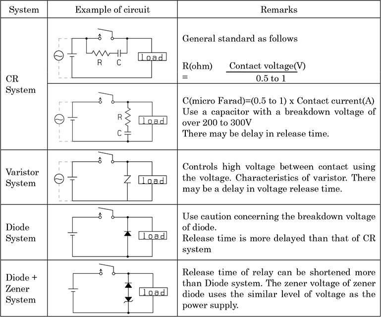
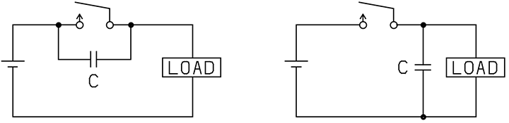
Mount the contact protection circuit near the contact point (within 50cm). Also, avoid using the following protection circuit.
Bad example
Mechanical Specifications / Mounting
- Note that if the stress more than specifications is applied to the switch during the operation, they might cause deformation and defects in electrical performance. Care shall be taken not to apply abnormal stress to the switch.
- Be sure to use the forced travel close to the position of the whole travel as much as possible.
- Use these switches at the travel position sufficiently away from the start position when they are set to ON.
- Note that the switch-returning force cannot be used as the mechanism driving force of any set.
- Take care not to apply external forces to the switch in the set mounting process.
- Take care not to apply pulling tension to terminal in connecting lead wire and connector. Also connector shall be inserted straightly without up and down forces.
- Use the mounting screws with specified diameter and length by applying the specified torque. Also, the spring washer is recommended to protect from loosing.
- Take care not to apply direct force to the push button or actuator of switch while the equipments and devices are in unloaded condition. Apply the horizontal force to the push button at the start of operation.
- Use proper PC board mounting hole dimensions meeting terminal arrangement and position.
- Insert the switch body to the specified mounting surface and mount it horizontally. If not mounted horizontally, the switch will malfunction.
- If the terminal is bent after inserting into the printed circuit board, take care not to apply stress to the switch body.
- Take care when fixing the printed circuit board by soldering it with terminals only, for there may be loosing off by vibration and break of circuit pattern.
- When mounting the switch with case frames, please solder the frames, too. If solder the terminals only, the switch with high operating force may be deformed and malfunction.
- When using the switches with bosses, please make the specified holes on the fitting board.
- Make certain that there is enough distance between each terminal and earth as the switches are fixed.
- In some products, there is a possibility that the lubricant used inside may leak out.Please carefully check the conditions of use and take this into consideration when designing and using the product.
Land pattern design / Soldering
- The land pattern design of PC board shall be made carefully based on the land pattern shown in the specification sheets, drawings, catalogues and so on.
- Characteristics of switch may change due to the warping of the circuit writing board. Consideration should be given to the pattern design and layout.
- In the mounting of the switch on the PC board, make the distance of 3mm or more from the edge of the PC board.
Depending on the mounting condition, the soldering flux may creep-up from the side body of the switch and cause the malfunction. - As there is the case that a part of the terminal exposes at the side of PC board mountuing, consideration should be given to the pattern design and layout.
- Conditions of soldering shall be confirmed under actual production conditions.
- Make the soldering according to the temperature and time specified in the specification sheets, catalogue and so on. If the soldering is made with the conditions out of the specifications, there may be the deformation of the mounting board and the composition parts of switches, the loose of terminals, detachment of the parts and the deterioration of the electrical characteristics.
- When wiring the lead wire to the terminal, give the suitable margin of length for wiring. Without the margin it may cause the defect due to the unnecessary load caused by the vibration and the shock.
- In the automatic soldering there is the possibility that soldering flux may penetrate into inside of the switch and may cause the failure of the contacts and the operation depending on the structure of the switches.
- Use of water-soluble soldering flux shall be avoided because it may cause corrosion of the metal parts and the deterioration of the strength and insulation of molding material.
- Do not wash the switches except being specified washable. If it is washes, the lubricant at the contact portion and mechanism part of switches will flow out, and it causes the defect of operation, and also substance of the washing solvent and the soldering flux remain in the inside of a switch which make the deterioration of the electrical characteristics.
- In the washing of washable type of switches, it shall be made when the temperature of the switches becomes room temperature after soldering.
- As long as the times of reflow soldering is not specified, it shall be one time.
- In case the soldering is done twice, the second soldering shall be made after the temperature at the first soldering portion becomes the room temperature. If it will be made consecutively, there is the possibility of the deformation of PC board and peripheral parts, the loose of terminals, detachment of the parts and the deterioration of the electrical characteristics.
- Before soldering switches with locking mechanism, release the locks. If they are soldered without releasing the locks, the soldering heat may deform the locking mechanism.
- In case of the soldering of the slide switches, it shall be made after the operating knob changes over completely.
If the soldering goes on in course of switching, operating force may fall greatly. - In case of the mounting on the through-hole type PC board, the influence of the heat stress to the switch becomes bigger than that of single side PC board. Be mindful of the soldering conditions thoroughly in advance.
- Please do not accumulate the wiring board on the printed wired board after mounting the switch. If it piles up, the terminal bend may occur which may cause the inconvenience of the insertion to the PC board.
- When soldering by auto dip is made, be sure to carry the confirmation test with actual conditions. For safety, the use of soldering flux preventive agent is recommended.
- Care shall be taken not to apply the stress to the terminal such as pressing, bending and pulling when soldering, to avoid the loose, deformation and the deterioration of electric and mechanical characteristics.
- In manual soldering, consider that the abnormal pressure of the soldering iron shall not be applied to the tip of the terminal as well do not apply any pressure for more than 1 minute after soldering.
- At the time of reflow soldering if the land area is excessive with too much solder, the increase of diffusion of flux may lead to the contact failure by the penetration of flux into inside of the switch. The dimension of the land area at the connecting portion shall be proper and the amount of the solder is also appropriate which can be recognized as an outline of the terminal.
- Since there is a possibility of the melting of the soldering flux and the penetration into inside of the switch after soldering, do not wipe off flux with the solvent.
Environment of usage
- Use the products in the operating temperature range specified in the catalogue and specification sheet.
In case of the long time use of the switch which incorporates the laminate in the high temperature more than specifications, the loose of the corking and fastening portion by the hear contraction and the deterioration of the insulation may cause. Moreover, lubricant flows out and the mechanical wear of the contact occurs which lead to the contact failure. When the switch is used under the operating temperature for a long time, the degree of viscosity of the lubricant becomes high which lead to the defect of operation and release operation.
And the water drop created by the deference of thermal conductivity of material causes the deterioration of the electrical characteristics. - Generally the contact of the switches are silver plated. Silver and silver plated material has the nature which forms the sulfured film by sulfur gas and the sulfured film causes the contact defect (increment of the contact resistance and contact failure).
In case the switches are used in the environments below, the switches with gold plated contact and sealed structure are recommended.
The environments and conditions of usage which create the sulfured film easily
・The places where the sulfur gas is always generating such as hot spring area.
・Constant usage in the environment of exhausted gas of automobile.
・Very less frequency of switching.( A few times a year)
・In the usage of the load with micro current level with less than 10 microampere.
Contacts are constructed so that the insulator between contacts is kept clean by mechanical friction. In case of very less frequency of the switching the sulfured film is likely to be created on the surface of the contacts which makes the unstable contact. - In case of the apparatus used in the dusty environment, the dust protective switches are recommended.
The normal switch without dust protection does not have sealing structure and it causes the contact failure by the fine dust entered from the gap of the switch body if it is used in the dusty environment.If wear particles or paper dust are generated during actual use, please take care to prevent them from entering through the switch opening. - When the switches are used in the watery environment and they are washed after soldering on the PC board, the water- protective type shall be used. The normal switch is not water-protective and it causes the defect of the contact and the failure of insulation and withstanding voltage by the lubricant used in the switch if it is used watery environment and is washed.
- If the switches are used in the following environment, the performance and the characteristics may have bad influence. Under the environment of silicone gas (siloxane) generated from silicone materials.
(May be generated from grease, oil, adhesive, rubber, spray, etc.)
Under the environment of corrosive gas such as Cl2, H2S, NO2, SO2, NH3
At the place of the possibility of the attachment of water-drop, moisture, salty water, oil, agent and organic solvent.
Under the places of direct sunshine and dusty environment.
Safety Standards
- The primary power supply changeover switches are regulated by safety standards, and the customers at particular destination request the safety standards approved by switch itself or as a set.
- It is regulated that the flame resisting material shall be used as insulation material depending on equipments and devices, applications and places to be used. The printed circuit board and outer material of primary power supply changeover switch are normally anti-heat resin. The safety standard (parts, equipments/devices) of each country requires the different grade of non-flame resisting, and please confirm the formal specification sheets.
Storage
- The storage warranty period for the switch is 6 months in unopened condition. Please store the switch in an environment with a environmental temperature of 10 to 35℃ a environmental relative humidity of 20 to 80%, no condensation, and away from direct sunlight.Please use immediately after opening the packaging. If storage is necessary after opening the packaging, please take appropriate measures to prevent moisture and gas, such as sealing the product in a plastic bag, and store it in an environment with a environmental temperature of 10 to 28℃ and a environmental relative humidity of 20 to 80%, away from sources of sulfur gas (cardboard, rubber products, etc.), and use within 3 days.Please note that long- term storage in a high temperature and humid environment may cause the silver-plated terminals to oxidize and a sulfide film to form,which may reduce solderability, and may also cause oxidation and rust of metal parts.
Peripheral Material of Equipments and Devices
- Please take care of the followings for the peripheral material of equipments and devices using these switches. Gases generated from the materials and inclusions of parts and materials may cause sulfidation, oxidation, and silicon oxide film formation on contacts and terminals, resulting in contact failure.
- Please use rubber-based materials and components that do not generate sulfur gas, oxidation gas, or silicone gas.Because, gas may generate due to the ambient environment such as vulcanizing condition and temperature, etc.
- Please use adhesives that do not generate sulfur gas, oxidation gas, or silicone gas.
- When using plywood,please use adhesives for plywood bonding that do not generate sulfur gas, oxidation gas, or silicone gas.
- Please use lubricants for the drive components inside the equipment that do not generate sulfur gas, oxidation gas, or silicone gas.
- For the packaging materials of the equipment, please also use materials that do not generate sulfur gas, oxidation gas, or silicone gas.
- When adhering chemicals such as coating material to the switch, please consult with us beforehand.
The above operation notes are quoted from the Safety Application Guide for Electronic Equipments and Devices, a technical report EIAJ RCR-5100 issued by the Electronic Information Technology Industrial Association.