Definitions of Solenoid Terms
Summary
DC solenoid is a mechanical part for converting the electric energy to mechanical energy using magnetic force generated by running electric current into electro-magnetic coil. Our DC solenoids with its high efficiency and reliability are now widely used for OA equipments, game machines and others and enjoy good reputation all over the world.
With reference to the special shaped ones besides our standard products, we are always trying to meet the customers requests and please feel free to contact us.
-
Classification of DC Solenoid
DP Type:General use pull-in type.
DM Type:Small holding type.
DL Type:Thinner self-latching type.
DF Type:Flapper type.
DV Type:Solenoid valve for sphygmomanometers.
-
Rating
DC solenoids are classified into continuous use and intermittent use according to the purpose and operating conditions.
a)Continuous use
Rating which does not exceed the stipulated temperature raise limit, even if the solenoid is continuously used at the rated voltage for a long time.b)Intermittent use
Rating which does not exceed the stipulated temperature limit when the solenoid is used at the rated voltage for the specified time.
In this case, several times of pull-in force can be obtained.
On the other hand, electric consumption power is increased, and the temperature is raised every second. Therefore, it is necessary to set the intermittent operating condition by using the current conducting ratio (Duty Ratio) as the following formula.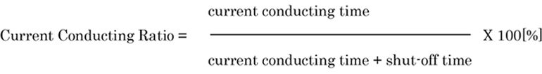
Longest current conducting time within one cycle normally differs on the operating conditionand shapes (dimensions), and please take care for this point.
-
Fluctuation of Pull-in and Holding Force
a)Influence on changes of temperature
Pull-in type solenoid is that ampere turn (AT) decreases and P/h (pull-in and holding) force decreases by the increase of excitation coil resistance caused by the rise of both excitation coil and ambient temperature. Therefore, when the temperature raise is expected at the time of use, it is necessary to take carefor selecting the proper solenoid with P/h force covering the decreased amount caused by the above.
In such case, the AT correction factor as below shall be of your help todecide the ampere turn needed for the requested pull-in force.Temperature Rise(deg.) -20 0 20 40 60 80 100 AT Correction Factor 0.92 1.00 1.08 1.16 1.24 1.32 1.40 (The above-mentioned temperature rise shows the increases from the room temperature of 20 [degree Celsius])
For instance, if the pull-in force of 1kg is required at the expected te mperature raise of 60 deg Celsius, the pull-in force at normal temperature of 1N x1.242=1.53N min. shall be considered.
b)Influence on the Fluctuation of the Voltage
The fluctuation of the power source voltage affects the ampere turn (AT) accordingly, and pull-in force changes. Consequently, it is necessary to select the solenoid which has enough P/h force satisfied in the operating voltage range.
So, it needs to select the solenoid holding enough pull-in force in the operating voltage range. Also, it is necessary to consider the change of the P/h force because the temperature of the solenoid body itself may change by the fluctuation of voltage. -
Measurement Method of Temperature Rise (based on JIS C4004)
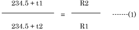
For the measurement of the temperature rise, generally the temperature calculation method using mercury or an alcohol thermometer is frequently used, but in the case of the temperature rise of the coil of relay or solenoid, inclination of the temperature rise of the coil towards the exterior from an interior is considerably large, and even if you measure the exterior temperature, it will be incomplete. Therefore, generally the measurement of the average temperature by the resistance method utilizing the resistance temperature factor of copper is adopted recently.● Resistance method
The resistance method calculation will be as follows
● If we seek for t2 by this formula,
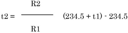 Temperature rised portion Sita is sought by t2 obtained by the above formula.

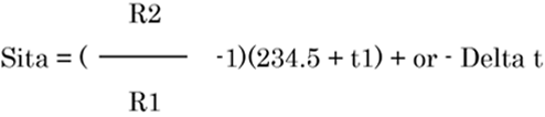
● If you make it a convenient form for calculation by changing the above formula (1) and (2), it will be the temperature raise calculation method by the resistance method.
 t1= C0il Temperature [degree Celsius] before it is energized
R1= Resistance [ohm] before it is energized
t2= Coil Temperature [degree Celsius] after energized
R2= Resistance [ohm] after energized
Delta t= Change of ambient temperature[degree Celsius]before it is energized, and after the temperature rised. It is to be deducted when the a mbient temperature is rised. On the contrary, to be added when the ambient temperature will fall. -
Influence on Residual Magnetism
Generally, even if we remove the impressed magnetic field by an extent of the chemical ingredients the manufacturing distortion caused when the material to be molded in the case of magnetic material, the magnetism will somewhat remain.
In case the residual magnetism is remained, movable iron cores will not return occasionally and it may become the problem of use. Theref ore, it is one of the important selection terms.
We are now adopting various kinds of methods of decreasing the residual magnetism, therefore, please tell us your operating condition beforehand. -
Regarding Input Terminal, Lead Wire and Lead Wire with Connector
Terminal Type and Lead Type Systems are available for its input part of the Solenoid.
The Terminal Type can be changed to the Lead Wire Type. Also, a connector can be connected to the tip end part of the lead wire on request.
As a special solenoid, 3-terminal solenoid is also available. It has a double wired coil which can be used as a suction coil and/or a keeping coil in case of pull-in type (DP Type), or as a suction coil and/or a return coil in case of latching type (DL Type). However, one of three terminals is common to all. -
Other Specifications
a)Insulation Resistance:More than 50 megohm at 250V DC(Normal Temperature & Humidity)(Between the Coil and Frame)
b)Insulating class:Standard products are all E class insulation.(Except Vinyl Electric Wire)