Definitions of Relay Terms
We explain the words that are used in this catalogue as follows. All items are based on JIS standards unless especially designated.
-
COILS
- Nominal coil voltage
- Since relay is normally used, it means the standard voltage is applied to the coil.
- Coil resistance
- The direct current resistance value of the coil, The value at temperature of 20 degree Celsius.
- Pick-up voltage and set voltage
- Pick-up voltage means the voltage when the relay reaches operated condition by gradually increasing the applied voltage to the relay coil in the unoperated condition of a single side stable type relay.
Set voltage means the voltage on a latching type relay, when it changes from reset to set condition.
- Drop-out voltage and reset voltage
- Drop-out voltage means the voltage when the applied voltage decreases gradually and the relay becomes unoperated condition after applied the nominal coil voltage in a single side stable type relay.
Reset voltage means the voltage of latching type relay's set condition of the reset coil, when its applied voltage is gradually increased (in case of 1-coil latching type relay, reverse polarity voltage) and it reaches reset condition. Also, pick-up voltage, set voltage, drop-out voltage and reset voltage shows at temperature of 20 degree Celsius.
- Electric power consumption
- This means the electric power which is consumed when nominal coil voltage is applied to the relay coil at 20 degree Celsisus.
- Maximum allowable voltage
- This means the maximum level of voltage to be applied to the relay coil continuously at 20 degree Celsisus. Furthermore, since it changes by the surrounding temperature and allowable contact current, please refer to the catalogue for the further details.
- Coil drive form
-
● Single side stable type
A relay for which the contact point changes responding to the energized or de-energized of the coil.● 2 coil latching type
A self maintaining-type relay with a set coil and a reset coil, total two coils. Even if the coil-applied voltage is cut off, this relay is able to maintain the operation condition.● 1 coil latching type
A self maintaining type relay which can be set or reset by applying the voltage of plus (+) and minus (-) on the one coil.
- Coil temperature rise
- The coil itself generates heat by the voltage applied to it and its temperature rises. In addition, the temperature rises indirectly by flowing electric current to the contact point.For further details, refer to the characteristics of coil temperature rise for the respective relays.
-
CONTACT
- Contact arrangement
-
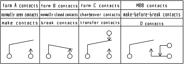
We call the contact mechanism and/or number of contact circuit Contact arrangement ”Contact arrangement”. Depending on the kind of contact mechanism, form A contacts (normally open contacts), from B contacts (normally closed contacts), form C contacts (changeover contacts), MBB contacts etc. are available.
For instance, 2C means that changeover contacts have 2 sets, MBB contacts is abbreviation for Make-Before-Break-Contacts”, and this is a contact point which has a mechanism in which form A contact closes before form B contact opens at the time of operation, and form B contacts closes before form A contacts opens when unoperation.
- Contact material quality
- Material for maintaining electrical contact and performance of opening and closing operation. Generally, silver is used as main material, having good electric conductivity and heat conductivity.
- Contact resistance
- Resistance where contact points contact each other and the combined resistance of conduct or resistance at the terminal and or contact spring.
The measurement is conducted by the voltage drop method (4-terminal method). (Based on JIS C5442.)
- Maximum switching voltage of contact
- Maximum voltage at which it is possible to open and close at the contact.
- Maximum switching current of contact
- Maximum electric current at which it is possible to open and close at the contact.
- Maximum switching electric power of contact
- Maximum load capacity value at which it is possible to open and close at the contact. In case of direct current, it is described as W and in case of alternate current, it is described as VA.
- Maximum allowable current
- The electric current value at which it is possible to circulate electricity continuously when the contact is closed.
- Rating nominal switching capacity (rated contact load)
- Value which becomes the standard specification for determining the performance of the switching part.
-
ELECTRICAL SPECIFICATIONS
- Operate time and set time
- Operate time means the time from when the rated voltage is applied to the coil of a single side stable type relay until either form A contact closes or form B contact opens, whichever is longer.
Set time means the time after applied to the rated voltage on the set coil of a latching type relay. It does not include the contact bounce time.
- Release time and reset time
- Release time means the time from when rated voltage is removed from the coil of a single stable type relay until either form B contacts closes or form A contacts opens, whichever is longer.
Reset time means the time after the rated voltage is applied to the reset coil of a latching type relay. It does not include the contact bounce time.
- Contact bounce time
-
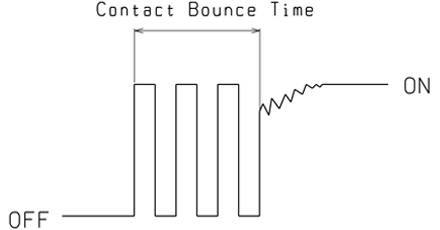
Intermittent switching of contact which may occur because of impact, vibration, etc. during operation or release time of relay is called Contact Bounce, and the said continuous time is called Bounce Time.

- Insulation resistance
- The resistance of the insulated part between the contact and coil terminal or the insulated part among several contact terminals, etc.
- Withstanding voltage
- The limit point at which insulation breakdown does not occur when high voltage is added between the insulated terminals for a certain time.
- Surge withstanding voltage
- The limits of durability against momentary abnormal voltage that occurs during the lightening or during the inductive load switching. Surge waveform is indicated by the standard surge withstand voltage waveform, etc., of 1.2 x 50 micro seconds. based on the JEC 212 1981.
-
MECHANICAL SPECIFICATIONS
- Shock resistance
- The limits of externally generated shock. There are two types of shock, functional shock which controls faulty operation and destruction shock which controls characteristics change and damage.
- Vibration resistant
- The limits to externally generated vibration. There are two different types of vibration, functional vibration which controls faulty operation and destruction vibration which controls characteristics change and damage.
-
LIFE EXPECTANCY
- Mechanical life
- The life when the relay is operated at the stipulated frequency without circulating electricity through the contact.
- Electrical life
- The life when the contact is connected to a rated load, and its relay is operated at stipulated switching frequency.
-
CONSTRUCTION
- Flux tight type
- A construction which prevents invasion of flux during the mounting on the printed circuit board. Automatic soldering is possible. It can not be washed for cleaning.
- Sealed type
- In addition to the construction which prevents the invasion of flux, this is a completely sealed construction which allows washing.